 Ryan Malloy
86a5db5b08
Ryan Malloy
86a5db5b08
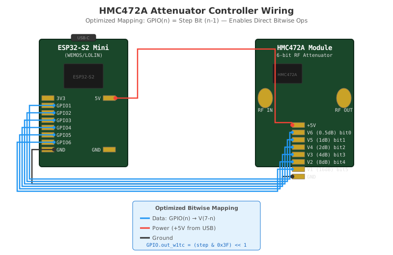
Rewire GPIO↔HMC472A so GPIO(n) = step bit (n-1):
  GPIO1→V6(0.5dB), GPIO2→V5(1dB), ... GPIO6→V1(16dB)

This enables single-instruction GPIO updates:
  GPIO.out_w1tc = (step & 0x3F) << 1
  GPIO.out_w1ts = (~step) & 0x7E

Replaces 28-line loop with 4-line bitwise code.
144 lines
7.8 KiB
XML
144 lines
7.8 KiB
XML



<?xml version="1.0" encoding="UTF-8"?>
|
|
<svg xmlns="http://www.w3.org/2000/svg" viewBox="0 0 800 520" width="800" height="520">
|
|
<defs>
|
|
<style>
|
|
.board { fill: #1a472a; stroke: #0d2818; stroke-width: 2; }
|
|
.board-label { font-family: monospace; font-size: 14px; font-weight: bold; fill: white; }
|
|
.pin-label { font-family: monospace; font-size: 11px; fill: #333; }
|
|
.pin-label-white { font-family: monospace; font-size: 10px; fill: #e0e0e0; }
|
|
.wire { stroke-width: 2.5; fill: none; }
|
|
.wire-data { stroke: #2196F3; }
|
|
.wire-power { stroke: #f44336; }
|
|
.wire-gnd { stroke: #333; }
|
|
.title { font-family: sans-serif; font-size: 18px; font-weight: bold; fill: #333; }
|
|
.subtitle { font-family: sans-serif; font-size: 12px; fill: #666; }
|
|
.note { font-family: sans-serif; font-size: 11px; fill: #555; }
|
|
.note-box { fill: #e3f2fd; stroke: #1976d2; stroke-width: 1; rx: 5; }
|
|
.header { fill: #333; }
|
|
.pin { fill: #c9a227; stroke: #8b7355; stroke-width: 1; }
|
|
.sma { fill: #c9a227; stroke: #8b7355; stroke-width: 1; }
|
|
.usb { fill: #333; stroke: #222; stroke-width: 1; }
|
|
.chip { fill: #1a1a1a; stroke: #333; stroke-width: 1; }
|
|
.code { font-family: monospace; font-size: 10px; fill: #1565c0; }
|
|
</style>
|
|
</defs>
|
|
|
|
<!-- Title -->
|
|
<text x="400" y="28" text-anchor="middle" class="title">HMC472A Attenuator Controller Wiring</text>
|
|
<text x="400" y="46" text-anchor="middle" class="subtitle">Optimized Mapping: GPIO(n) = Step Bit (n-1) — Enables Direct Bitwise Ops</text>
|
|
|
|
<!-- ESP32-S2 Mini Board -->
|
|
<rect x="80" y="80" width="180" height="260" rx="5" class="board"/>
|
|
<text x="170" y="102" text-anchor="middle" class="board-label">ESP32-S2 Mini</text>
|
|
<text x="170" y="116" text-anchor="middle" class="pin-label-white">(WEMOS/LOLIN)</text>
|
|
|
|
<!-- USB-C on S2 Mini -->
|
|
<rect x="145" y="70" width="50" height="14" rx="3" class="usb"/>
|
|
<text x="170" y="80" text-anchor="middle" style="font-size:8px;fill:#888;">USB-C</text>
|
|
|
|
<!-- ESP32 chip representation -->
|
|
<rect x="130" y="130" width="80" height="50" rx="2" class="chip"/>
|
|
<text x="170" y="160" text-anchor="middle" style="font-size:9px;fill:#666;">ESP32-S2</text>
|
|
|
|
<!-- S2 Mini Pin Header (left side) -->
|
|
<g transform="translate(85, 195)">
|
|
<rect x="0" y="0" width="25" height="10" class="pin"/><text x="30" y="9" class="pin-label-white">3V3</text>
|
|
<rect x="0" y="15" width="25" height="10" class="pin"/><text x="30" y="24" class="pin-label-white">GPIO1</text>
|
|
<rect x="0" y="30" width="25" height="10" class="pin"/><text x="30" y="39" class="pin-label-white">GPIO2</text>
|
|
<rect x="0" y="45" width="25" height="10" class="pin"/><text x="30" y="54" class="pin-label-white">GPIO3</text>
|
|
<rect x="0" y="60" width="25" height="10" class="pin"/><text x="30" y="69" class="pin-label-white">GPIO4</text>
|
|
<rect x="0" y="75" width="25" height="10" class="pin"/><text x="30" y="84" class="pin-label-white">GPIO5</text>
|
|
<rect x="0" y="90" width="25" height="10" class="pin"/><text x="30" y="99" class="pin-label-white">GPIO6</text>
|
|
<rect x="0" y="105" width="25" height="10" class="pin"/><text x="30" y="114" class="pin-label-white">GND</text>
|
|
</g>
|
|
|
|
<!-- S2 Mini Pin Header (right side) -->
|
|
<g transform="translate(210, 195)">
|
|
<rect x="0" y="0" width="25" height="10" class="pin"/><text x="-5" y="9" text-anchor="end" class="pin-label-white">5V</text>
|
|
<rect x="0" y="105" width="25" height="10" class="pin"/><text x="-5" y="114" text-anchor="end" class="pin-label-white">GND</text>
|
|
</g>
|
|
|
|
<!-- HMC472A Module Board -->
|
|
<rect x="520" y="80" width="200" height="260" rx="5" class="board"/>
|
|
<text x="620" y="102" text-anchor="middle" class="board-label">HMC472A Module</text>
|
|
<text x="620" y="116" text-anchor="middle" class="pin-label-white">6-bit RF Attenuator</text>
|
|
|
|
<!-- HMC472A chip representation -->
|
|
<rect x="555" y="130" width="60" height="40" rx="2" class="chip"/>
|
|
<text x="585" y="155" text-anchor="middle" style="font-size:8px;fill:#666;">HMC472A</text>
|
|
|
|
<!-- SMA Connectors -->
|
|
<ellipse cx="540" cy="200" rx="15" ry="20" class="sma"/>
|
|
<text x="540" y="228" text-anchor="middle" class="pin-label-white">RF IN</text>
|
|
<ellipse cx="700" cy="200" rx="15" ry="20" class="sma"/>
|
|
<text x="700" y="228" text-anchor="middle" class="pin-label-white">RF OUT</text>
|
|
|
|
<!-- HMC472A Control Header (8-pin) - optimized order -->
|
|
<g transform="translate(595, 250)">
|
|
<rect x="0" y="0" width="25" height="10" class="pin"/><text x="30" y="9" class="pin-label-white">+5V</text>
|
|
<rect x="0" y="15" width="25" height="10" class="pin"/><text x="30" y="24" class="pin-label-white">V6 (0.5dB) bit0</text>
|
|
<rect x="0" y="30" width="25" height="10" class="pin"/><text x="30" y="39" class="pin-label-white">V5 (1dB) bit1</text>
|
|
<rect x="0" y="45" width="25" height="10" class="pin"/><text x="30" y="54" class="pin-label-white">V4 (2dB) bit2</text>
|
|
<rect x="0" y="60" width="25" height="10" class="pin"/><text x="30" y="69" class="pin-label-white">V3 (4dB) bit3</text>
|
|
<rect x="0" y="75" width="25" height="10" class="pin"/><text x="30" y="84" class="pin-label-white">V2 (8dB) bit4</text>
|
|
<rect x="0" y="90" width="25" height="10" class="pin"/><text x="30" y="99" class="pin-label-white">V1 (16dB) bit5</text>
|
|
<rect x="0" y="105" width="25" height="10" class="pin"/><text x="30" y="114" class="pin-label-white">GND</text>
|
|
</g>
|
|
|
|
<!-- Wiring: Power (5V) - Red -->
|
|
<path d="M 235 200 H 280 V 100 H 560 V 250 H 595" class="wire wire-power"/>
|
|
<circle cx="235" cy="200" r="4" fill="#f44336"/>
|
|
<circle cx="595" cy="255" r="4" fill="#f44336"/>
|
|
|
|
<!-- Wiring: GND - Black -->
|
|
<path d="M 110 305 H 65 V 375 H 575 V 360 H 595" class="wire wire-gnd"/>
|
|
<circle cx="110" cy="305" r="4" fill="#333"/>
|
|
<circle cx="595" cy="360" r="4" fill="#333"/>
|
|
|
|
<!-- Straight-through data wiring (optimized - no crossovers!) -->
|
|
<!-- GPIO1 → V6 -->
|
|
<path d="M 110 215 H 60 V 365 H 590 V 270 H 595" class="wire wire-data"/>
|
|
<circle cx="110" cy="215" r="3" fill="#2196F3"/>
|
|
<circle cx="595" cy="270" r="3" fill="#2196F3"/>
|
|
|
|
<!-- GPIO2 → V5 -->
|
|
<path d="M 110 230 H 55 V 370 H 585 V 285 H 595" class="wire wire-data"/>
|
|
<circle cx="110" cy="230" r="3" fill="#2196F3"/>
|
|
<circle cx="595" cy="285" r="3" fill="#2196F3"/>
|
|
|
|
<!-- GPIO3 → V4 -->
|
|
<path d="M 110 245 H 50 V 375 H 580 V 300 H 595" class="wire wire-data"/>
|
|
<circle cx="110" cy="245" r="3" fill="#2196F3"/>
|
|
<circle cx="595" cy="300" r="3" fill="#2196F3"/>
|
|
|
|
<!-- GPIO4 → V3 -->
|
|
<path d="M 110 260 H 45 V 380 H 575 V 315 H 595" class="wire wire-data"/>
|
|
<circle cx="110" cy="260" r="3" fill="#2196F3"/>
|
|
<circle cx="595" cy="315" r="3" fill="#2196F3"/>
|
|
|
|
<!-- GPIO5 → V2 -->
|
|
<path d="M 110 275 H 40 V 385 H 570 V 330 H 595" class="wire wire-data"/>
|
|
<circle cx="110" cy="275" r="3" fill="#2196F3"/>
|
|
<circle cx="595" cy="330" r="3" fill="#2196F3"/>
|
|
|
|
<!-- GPIO6 → V1 -->
|
|
<path d="M 110 290 H 35 V 390 H 565 V 345 H 595" class="wire wire-data"/>
|
|
<circle cx="110" cy="290" r="3" fill="#2196F3"/>
|
|
<circle cx="595" cy="345" r="3" fill="#2196F3"/>
|
|
|
|
<!-- Legend -->
|
|
<rect x="270" y="410" width="260" height="100" rx="5" class="note-box"/>
|
|
<text x="400" y="428" text-anchor="middle" style="font-weight:bold;" class="note">Optimized Bitwise Mapping</text>
|
|
|
|
<line x1="285" y1="445" x2="305" y2="445" stroke="#2196F3" stroke-width="3"/>
|
|
<text x="310" y="449" class="note">Data: GPIO(n) → V(7-n)</text>
|
|
|
|
<line x1="285" y1="465" x2="305" y2="465" stroke="#f44336" stroke-width="3"/>
|
|
<text x="310" y="469" class="note">Power (+5V from USB)</text>
|
|
|
|
<line x1="285" y1="485" x2="305" y2="485" stroke="#333" stroke-width="3"/>
|
|
<text x="310" y="489" class="note">Ground</text>
|
|
|
|
<text x="400" y="503" text-anchor="middle" class="code">GPIO.out_w1tc = (step & 0x3F) << 1</text>
|
|
</svg>
|